Plating Tank Temperature Mapping Under Production Load
Map temperature across a plating tank under representative loads. Compare the controller reading with independent points and specify recovery evidence.
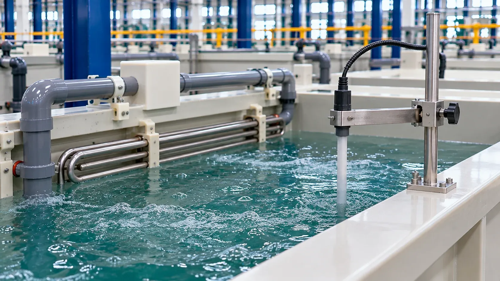
Map a plating tank's temperature where the parts actually run and over the period the route requires. Compare the controller probe with independent, verified readings at defined locations. Include representative loading and recovery so the equipment quote addresses both the working zone and the time needed to return to the approved window.
ES-PRO editorial team · Updated 11 November 2026
A controller shows the condition at its sensor. A loaded tank can need evidence from other positions and times. The NIST industrial thermometer calibration page provides measurement context for calibrated probes. Use the approved process window and site procedures for the actual tank and test setup.
Define the working zone and measurement system
Mark the tank plan, normal liquid level, loaded rack footprint, controller probe and circulation entry or return. Select points that represent where parts sit, including any expected gradients. Record depth and distance from the rack or vessel reference so the test can be repeated. Confirm that independent probes, leads and supports are suitable for the process and approved for the test.
Document the probe and readout as a measurement system. Compare instrument IDs, calibration status and any applied corrections. Use synchronized readings when comparing spatial differences during a transient. If a moving probe is used, record the sequence and allow for time and response differences in interpreting the map.
Test window | Record | Reason to include it |
|---|---|---|
Stable operation before loading | Controller and independent point readings | Establish the spatial and instrument baseline |
Representative load enters | Time, load identity and agreed point readings | Observe the temperature response during the operating cycle |
Before the next scheduled load | Readings and elapsed recovery time | Check whether the proposed release interval is feasible |
Repeated load sequence | Trends across similar racks | Check whether the process drifts under the expected production pattern |
Worked example with a center-to-end difference
Suppose the controller returns to its normal reading after a representative rack enters. A second instrument at the far end of the loaded zone still reads outside the project window. Check that both readings refer to the same time and that the far-end measurement is repeatable. Compare with a second approved reference or a location swap when feasible. Record any uncertainty relevant to the release decision.
If the difference persists at that point, review the loaded flow pattern, heat transfer, sensor position and operating sequence. A higher heater rating may change recovery time while leaving the spatial difference unresolved. Ask the process and equipment teams to compare circulation and heat transfer options using the same load and mapping points.
If the offset follows the independent instrument when it moves, investigate the instrument and setup before modifying the tank. Keeping both hypotheses in the log helps the team make a controlled change and measure its effect.
Agree how readings will be compared
Use a common time reference and name the events that start each comparison. Examples are rack entry, first circulation reading after entry and the next planned release point. Averages across the whole cycle can conceal the interval when the working zone is furthest from the approved window. Keep the time series for each named location.
Repeat with the approved part family that places the greatest expected thermal load on the tank. Record how that family was selected. If the available trial load is smaller, label the result with its actual basis and agree what still needs to be shown during production qualification.
Specify recovery and measurement evidence
Define what the supplier should show under the representative load: the approved temperature window, named points, time intervals and criterion for recovery. State the production cadence and initial conditions. A dry control check can verify display, alarms and data logging. Use the agreed wet or representative thermal test for evidence about the working zone.
Record tank ID · load and stage · measurement point and depth · instrument ID · time · controller reading · independent reading · circulation state · recovery decision. Ask which probes and access points the line supplies and who provides independent measurement during acceptance.
Review the tank heater guide for heater duty and the plating pump guide for circulation interfaces. Keep the map tied to the temperature and loading conditions the equipment must demonstrate.
Use the plating line layout guide to reserve safe measurement access and confirm where the temporary or permanent probe supports belong.
FAQ
How many points should a tank temperature map have?
Choose points that represent the loaded working zone and any expected gradients. Agree the test locations and repeat conditions with the process owner.
Does a stable controller reading prove the tank is ready for another rack?
Use the controller reading with the validated recovery criteria for the working zone and representative loading sequence.
Should mapping be repeated after a retrofit?
Repeat the agreed check when an approved change can affect the relevant temperature pattern or recovery, such as a new load or circulation arrangement.
Discuss a plating tank temperature map
Share the working-zone sketch and load sequence. Include the project window and any available readings. Send layouts by sales email, or discuss the project on WhatsApp.
Image note: AI-generated editorial photography illustrates equipment or workpiece contexts; it is not an ES-PRO installation, customer reference or evidence of coating performance.